摄像机标定 标定程序与步骤 一个标定程序应该包括:M ≥ 6 M\geq 6 M ≥ 6 ( X i , Y i , Z i ) i = 1 , 2 , . . . , M (X_i,Y_i,Z_i)\;i=1,2,...,M ( X i , Y i , Z i ) i = 1 , 2 , ... , M 最小二乘法 减小误差)( x i , y i ) i = 1 , 2 , . . . , M (x_i,y_i)\;i=1,2,...,M ( x i , y i ) i = 1 , 2 , ... , M
综上所述,相机标定可大致分为以下 4 步,且每一步都有需要标定的参数。
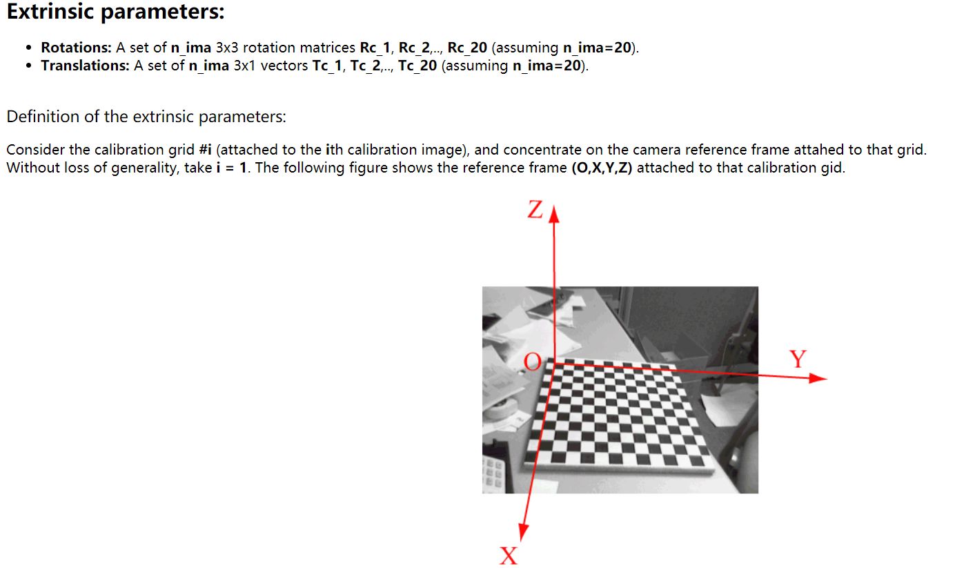
标定旋转矩阵R \boldsymbol R R T \boldsymbol T T 标定相机焦距λ \lambda λ 标定镜头的径向失真系数k k k 标定不确定性图像尺度因子μ \mu μ 上述参数中,具体又可分为两类:外部参数 和 内部参数 。
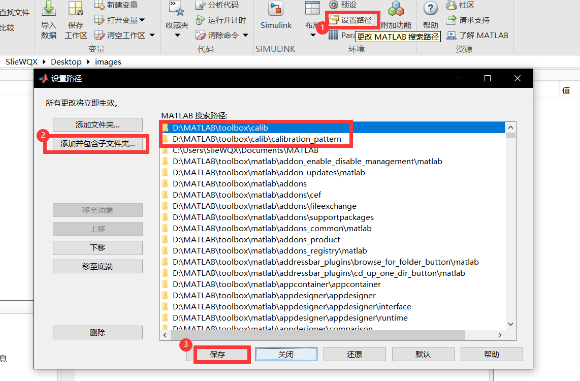
外部参数 ,又称相机姿态参数 。利用欧拉角将旋转矩阵R \boldsymbol R R ( θ , ϕ , ψ ) (\theta,\phi,\psi) ( θ , ϕ , ψ ) T \boldsymbol T T ( T x , T y , T z ) (T_x,T_y,T_z) ( T x , T y , T z ) 内部参数 ,即 相机自身的参数 。包括 5 个参数:焦距λ \lambda λ k k k λ \lambda λ O m , O n O_m,O_n O m , O n MATLAB实验 安装工具包 这里我们使用 Matlab R2021b 进行实验,并且将工具包解压到 D:\MATLAB\toolbox\calib
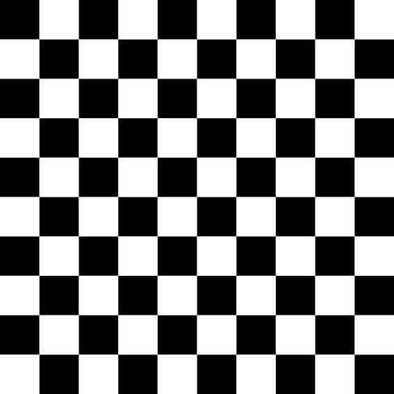
拍摄图片 因为本实验基于 张正友标定法 ,因此我们需要绘制并打印黑白相间的棋盘格 作为相机标定板。
这里我们参考了CSDN网友 None072 的方法,利用Python 和 Photoshop CC 绘制并打印了规格为:10 × 10 10\times 10 10 × 10 20 m m × 20 m m 20mm\times 20mm 20 mm × 20 mm
代码和结果图如下:
1
2
3
4
5
6
7
8
9
10
11
12
13
14
15
import cv2import numpy as npsize = 200 boardx = size * 10 boardy = size * 10 canvas = np.zeros((boardy, boardx, 1 ), np.uint8) for i in range (0 , boardx): for j in range (0 , boardy): if (int (i/size) + int (j/size)) % 2 != 0 : canvas[j, i] = 255 cv2.imwrite("chessboard.png" , canvas)
我们将图片以 取消适应边框 的方式进行打印 ,以保证在PS里设置的尺寸能在现实中保持不变。
之后,拍摄了12张 不同角度不同位置的图片,用于导入MATLAB进行分析。
导入图片 由于是用手机拍摄,图片的命名并不规范,因此我们编辑.bat文件,使得 Windows10 的 实验设备 能通过我们编写的DOS命令实现批量重命名 。
此处我们将图片前缀统一命名为 img.
1 2 3 4 5 6 @echo off&setlocal EnableDelayedExpansion set a=1for /f "delims=" %%i in ('dir /b *.jpg' ) do ( if !a! LSS 10 (ren "%%i" "img00!a!.jpg" ) else if !a! LSS 100 (ren "%%i" "img0!a!.jpg" ) else ren "%%i" "img!a!.jpg" set /a a+=1 )
结果如下:calib_gui。
随后,选择 Standard 模式,然后选择 Image names,根据提示依次输入图片的前缀img和后缀jpg:
1
2
3
4
5
6
7
8
9
. img002.jpg img005.jpg img008.jpg img011.jpg .. img003.jpg img006.jpg img009.jpg img012.jpg img001.jpg img004.jpg img007.jpg img010.jpg 批量重命名.bat Basename camera calibration images (without number nor suffix): img Image format: ([]='r' ='ras' , 'b' ='bmp' , 't' ='tif' , 'p' ='pgm' , 'j' ='jpg' , 'm' ='ppm' ) jpg Loading image 1...2...3...4...5...6...7...8...9...10...11...12... done
导入成功之后,对图片进行读取:Read images
提取角点 点击Extract grid corners,根据命令行窗口的提示,设置图片个数和窗口大小以及是否自动提取角点(方格数)。这里均可回车默认。
1
2
3
4
5
6
7
8
Extraction of the grid corners on the images Number(s) of image(s) to process ([] = all images) = Window size for corner finder (wintx and winty): wintx ([] = 36) = winty ([] = 36) = Window size = 73x73 Do you want to use the automatic square counting mechanism (0=[]=default) or do you always want to enter the number of squares manually (1,other)?
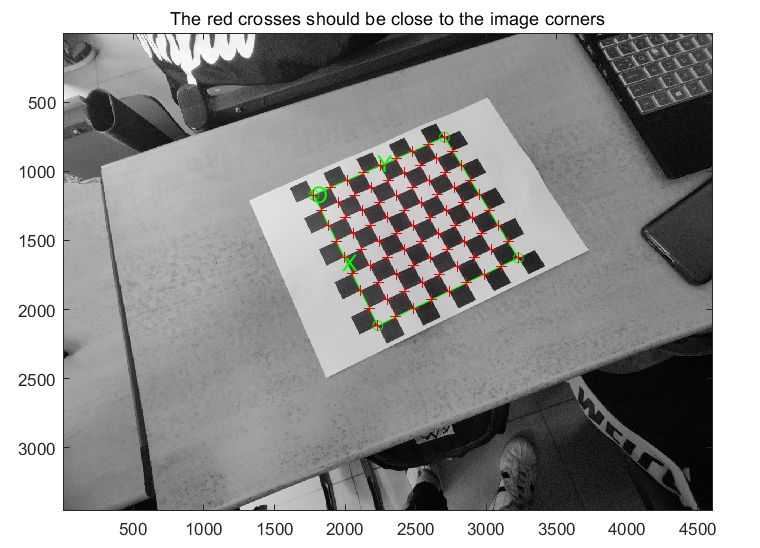
之后,程序要求我们手动标注棋盘的四个角。这里我们使用内圈的四个角。
之后命令行窗口需要我们输入每一个格子的边长大小,这里就是20mm了。此外还会询问:Need of an initial guess for distortion?|需要对失真进行初步猜测吗?
1
2
3
4
5
6
Size dX of each square along the X direction ([]=100mm) = 20 Size dY of each square along the Y direction ([]=100mm) = 20 If the guessed grid corners (red crosses on the image) are not close to the actual corners, it is necessary to enter an initial guess for the radial distortion factor kc (useful for subpixel detection) Need of an initial guess for distortion? ([]=no, other=yes) Corner extraction...
第一次填完dX,dY之后,就不许再次填写了。我们需要重复上述操作直到12张图片都处理结束,并且成功(出现done提示)。
标定测算 回到可视化窗口,选择Calibration则就能计算并在命令行窗口显示相机内参。
1
2
3
4
5
6
7
8
9
Calibration results after optimization (with uncertainties): Focal Length: fc = [ 2367.95089 2365.78295 ] +/- [ 32.46621 32.22575 ] Principal point: cc = [ 2303.76724 1751.05028 ] +/- [ 17.12505 18.03928 ] Skew: alpha_c = [ 0.00000 ] +/- [ 0.00000 ] => angle of pixel axes = 90.00000 +/- 0.00000 degrees Distortion: kc = [ 0.02064 -0.02930 -0.00251 0.00311 0.00000 ] +/- [ 0.01773 0.04392 0.00265 0.00267 0.00000 ] Pixel error: err = [ 1.91373 2.36112 ] Note: The numerical errors are approximately three times the standard deviations (for reference).
结果 焦距 主点位置O m O_m O m 主点位置O n O_n O n 失真系数k k k 2367.95 2367.95 2367.95 2303.77 2303.77 2303.77 1751.05 1751.05 1751.05 0.02 0.02 0.02
在程序给出的结果中,fc(1) 和 fc(2) 是以水平和垂直像素为单位表示的焦距,在正方形棋盘情况下,二者大小一般相差不大,这里我们取了前者。 在程序给出的结果中,失真系数包括径向和切向失真,存储在 5x1 向量kc 中,这里我们取了第一个。 以上数据除失真系数外,单位均为mm。 其他 如果自动找角点的位置不准确,如何处理? 在程序运行时,有这样的提示:If the guessed grid corners (red crosses on the image) are not close to the actual corners, it is necessary to enter an initial guess for the radial distortion factor kc (useful for subpixel detection)
意思是:如果猜测的网格角点(图像上的红色叉号)与实际角点不接近,则需要输入径向畸变因子 kc 的初始猜测值(对亚像素检测有用)。所以我们可以通过这种方式进行校准。
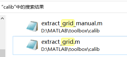
当然,实际中我们不一定能设定出很好的kc的初始猜测数据。这时我们可以尝试从源码出发,通过检索工具箱的文件,我们发现了如下文件:
可以尝试更改源码的一些参数,甚至是自己设计其他的角点检测算法 如 SUSAN 算法 等进行代替。
如何利用该程序获取外参? 在工具箱的官网 中清晰地给出了外部参数 在程序中的变量名。
于是,我们可以直接在导出的结果之中 找到 12 张图的旋转矩阵 R R R 平移矢量 T T T 欧拉角
参考 利用Python-OpenCV及PS制作棋盘格标定板|CSDN Win10如何批量修改文件名,实现向后加固定的数字|CSDN Camera Calibration Toolbox for Matlab